
Wiring guide
What to connect sensors, locks, lights and effects: what goes on the inputs, what goes on the outputs and what they can take
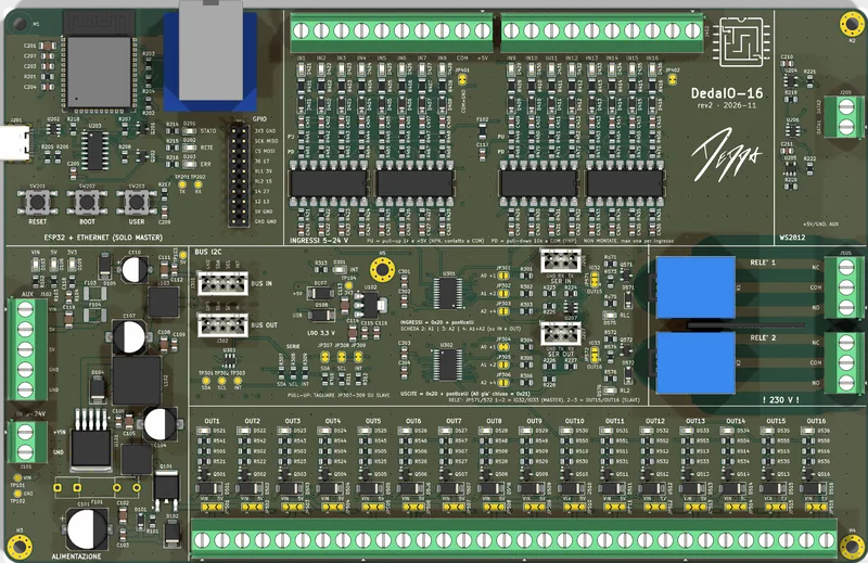
DedaIO-16 is built for the parts you actually find in escape rooms: buttons and reed switches, photo eyes and industrial sensors, maglocks and solenoids, lights, fog machines and LED strips. Almost everything wires straight to the screw terminals, with no modules in between.
Start with the inputs Back to the board
- 5-24 V on the inputs
- 2 A per output
- 2 dry-contact relays
- 2 WS2812 lines
Inputs · dry contacts
Buttons, reed switches, limit switches
Anything that closes a contact connects with two wires: one to the +5V
terminal at the end of the input block, the other to the input. When the contact closes
the channel LED lights up and the game knows. Nothing needs powering: the 5 V comes from
the board, protected by a resettable fuse.
- Push buttons, including arcade and mushroom buttons, switches, toggles and key switches
- Reed switches with magnets: drawers, hatches, objects placed in the right spot
- Microswitches and limit switches: levers, knobs, pieces to insert
- Pressure mats, ball tilt and shake sensors
- Contacts of existing devices: locks with a status contact, code keypads with a relay output
Inputs · powered sensors
Industrial sensors at 12 or 24 V
The inputs take 5 to 24 V signals and are optically isolated: three-wire sensors are powered from the board's AUX terminal or from their own supply, the output goes to the input and 0 V to the common. The 16 inputs are split into two groups of 8, each with its own common: cutting a jumper separates the group from the board ground.
- Inductive and capacitive proximity sensors, including M12 and M18
- Photo eyes, light barriers and lasers with receivers
- PIR motion detectors and vibration sensors with a relay output
- Magnetic and Hall effect sensors with a digital output
- Standalone RFID and NFC readers, fingerprint readers and radio modules with a relay or voltage output
- Outputs of PLCs, timers and other 5 to 24 V controllers
PNP sensors connect directly. For NPN open collector sensors the board has pull-up resistor positions on every channel: we fit them on request.
Outputs · locks and actuators
Maglocks, electric strikes, solenoids
Each output has two terminals: + and − of the load. The load
goes in between, nothing else: the flyback diode that protects against coils and
electromagnets is already on the board. Each channel handles up to 2 A and has its own LED.
- 12 or 24 V maglocks (door electromagnets)
- Electric locks and strikes, latch or bolt
- Push-pull solenoids for hidden releases and mechanisms
- Solenoid valves for water, air and fog
- Electromagnets that hold and drop objects
On exit doors use locks that open when power is lost and an emergency button that does not depend on the board: player safety must never depend on firmware.
Outputs · lights and effects
Lights, fans, buzzers, small motors
Each output's voltage is chosen channel by channel with a solder jumper: the board's supply voltage (12 or 24 V) or 5 V. A 12 V maglock and a 5 V buzzer can share the same board.
- 12/24 V lamps and LED spotlights, single-colour LED strips, UV light
- Fans, vibration motors, small gear motors
- Buzzers, sirens and beacons
- 5 V modules: small audio players, lasers, signs
The outputs are on/off: for fades and colours there are the WS2812 strips. Motors turn in one direction only; to reverse them, use the two relays.
Outputs · loads above 2 A
Heavy loads: a second stage
For a big motor, a 3 A or larger electromagnet or a long single-colour LED strip, the
board's output doesn't drive the load itself but a power module. The module is wired like
any other load: input + to the output's +, input −
to its −. Output on, module on.
- MOSFET modules with an opto-isolated input: the load has its own power supply and ground, and the heavy current never flows through the board
- DC solid-state relays (SSR), silent and with no contacts to wear out
- Contactors for 230 V loads, driven by the board's two relays
The module input needs only a few mA. Avoid MOSFET modules without an opto-isolator whose transistor (IRF520 and similar) is driven directly: with 5 V on the gate it is only half on and heats up.
Relays · dry contacts
Everything else goes through the relays
The two relays have changeover contacts COM, NO and
NC, separated from the rest of the board: they close a circuit that has
nothing to do with the board's power supply.
- Remote trigger input of fog, bubble and snow machines
- Starting audio and video players, projectors and other devices with a contact input
- Contacts to another controller, the alarm system or the room's electrical panel
- Loads with their own power supply, even at a different voltage
- Reversing a DC motor, with both relays together
The relays are rated 10 A. Mains wiring must be done by an electrician; for large loads the relay should drive a contactor.
Addressable LEDs
WS2812 strips, rings and matrices
Two 5 V data outputs, already level-shifted for LEDs, drive WS2812B and compatible strips and rings: every LED has its own colour. Great for progress indicators, panels that change colour, energy flowing through pipes and room ambience.
- 5 V WS2812B / SK6812 strips, rings, matrices and single pixels
- Colours and effects driven by the game or by the room software
- Short strips powered from the 5 V AUX terminal
- Long strips with their own 5 V supply and a ground shared with the board
One LED at full white draws about 60 mA: 60 LEDs on together already exceed 3 A, so beyond a few dozen LEDs you need a dedicated power supply.
Special projects
When you need something more
For custom firmware the board leaves a header with ESP32 GPIOs, the SPI bus, 3.3 V and 5 V, plus two serial ports to other boards. It takes modules that speak a protocol instead of a simple contact.
- Serial MP3 players for audio synchronised with the game
- RFID readers that tell which object was placed, not just whether one is there
- I2C and SPI sensors, displays, analogue sensors
- ESP32 Wi-Fi and Bluetooth LE for wireless props
These are 3.3 V logic signals: we design these connections together with the firmware.
Electrical limits
What it can take
| Power supply | 9-24 V DC (26 V maximum), 6.3 A slow-blow fuse for the whole board |
|---|---|
| Inputs | 16 optically isolated, 5 to 24 V signal (26 V maximum), about 6 mA at 24 V; 2 commons of 8 channels, separable from ground |
| +5V for contacts | one terminal per input block, 200 mA in total with a resettable fuse |
| Outputs | 16 low-side MOSFETs, up to 2 A per channel, at supply voltage or 5 V chosen per channel; flyback diode and LED on every channel |
| Total current | loads switched on together from the supply voltage go through the 6.3 A fuse; at 5 V there are 3 A in total, board included |
| AUX terminal | supply voltage and 5 V for sensors and strips, each with a 2 A resettable fuse |
| Relays | 2, changeover contacts COM / NO / NC (10 A relays), separated from the board |
| Addressable LEDs | 2 WS2812 data lines at 5 V; long strips need their own power |
| Terminals | screw terminals, 5.08 mm pitch |
Examples
Typical puzzles, wired
| Objects in the right place | reed switches and magnets hidden in the objects on the inputs; hatch maglock and spotlight on the outputs |
|---|---|
| Lever combination | switches and toggles on the inputs; drawer lock and a buzzer for wrong answers |
| RFID altar | standalone RFID reader with a relay output on one input; electromagnet that drops the key |
| Panel to repair | buttons and patch plugs on the inputs; WS2812 ring turning green and a relay starting the fog machine |
| Laser corridor | light barriers or lasers with receivers on the inputs; siren and red lights on the outputs |
| Final door | fail-safe maglock on one output, emergency button wired directly to the maglock |
FAQ
Wiring questions
Can I connect an NPN sensor?
Yes. PNP sensors and sensors with a 5 to 24 V voltage output connect directly. For NPN open collector sensors the board has pull-up resistor positions on every channel: we fit them on request, and that input's logic is inverted.
Can I switch 230 V loads?
The 16 outputs are for DC loads only (5 V or the board's supply voltage, 12 or 24 V). The two relays have dry contacts: mains wiring must be done by an electrician, and for large loads the relay should drive a contactor.
Can I dim the lights?
The 16 outputs are on/off. For colours, fades and effects there are two outputs for WS2812 LED strips and rings; dimmable lamps need an external dimmer.
Can I drive a load above 2 A?
Yes, with a second stage: the board's output drives a MOSFET module with an opto-isolated input or a DC solid-state relay, wired like any other load, and the module powers the load from its own supply. For 230 V loads use the board's relays with a contactor.
How many locks can be on at the same time?
Each output handles up to 2 A; all loads switched on together from the supply voltage go through the board's 6.3 A fuse and must fit the power supply rating. A typical maglock draws a few hundred mA, so you can run quite a few.
Not sure how to wire your puzzle?
Send us the list of sensors and actuators: we'll tell you how to wire them and how many boards you need.